The One About Choosing an Antenna
Is a dipole better than a vertical? Is an inverted "y" better than a flattop dipole? What about long wires, inverted “L’s”’, loops, discones, and all the others.... which one is best for me?
The answers to these questions depend on the desired results. Do you want to work DX? Are you trying to work across town? Are your desired contacts 50 to 500 miles away? What band are you using? What time of day? These are some of the considerations that must be decided upon before answers can be given, because the best antenna for one purpose is most likely not the best for another purpose, Here's why:
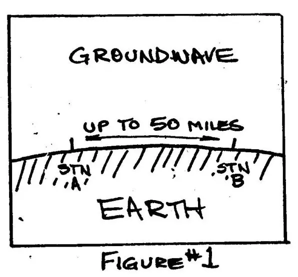
Local contacts (1 to 50 miles) require that the signal travel across the surface of the earth (groundwave) as in Figure #1.
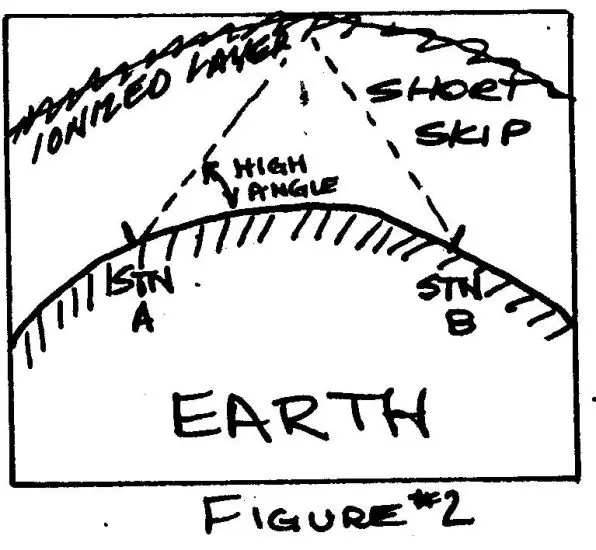
Contacts from 50 to 500 miles will require reflection of signals at high angles as in Figure #2
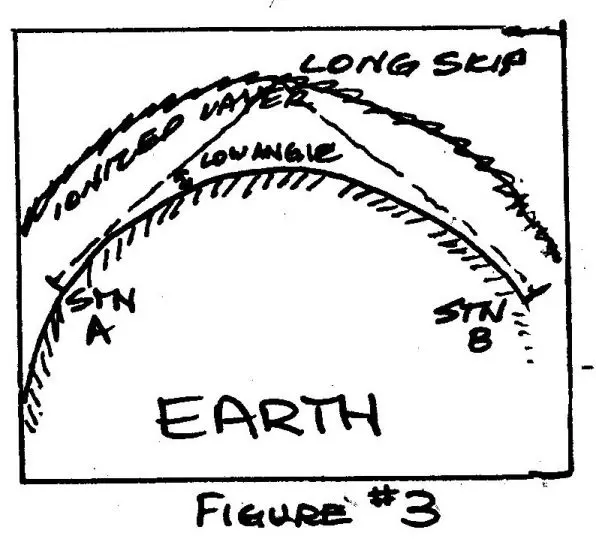
The longest DX contacts are most easily made by reflecting signals at low angles as in Figure #3.
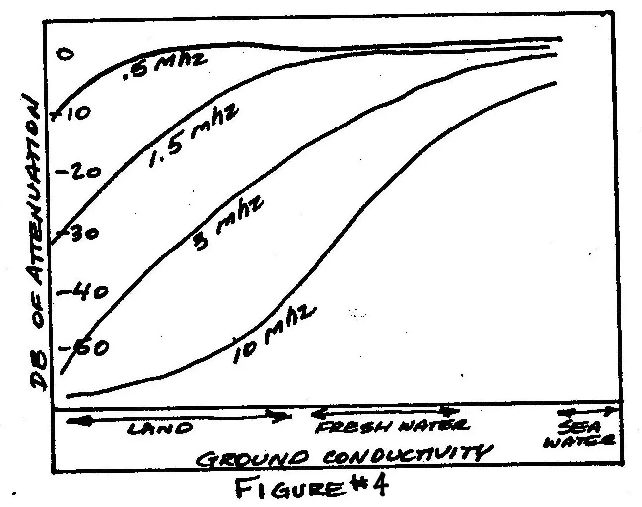
Each antenna configuration produces radiated signals at different angles and with varying amounts of groundwave. Other factors than antennas affect the results, of course. For instance, groundwave attenuation varies inversely with frequency. In other words, using identical antennas and power, groundwave signals will be stronger on 160 meters than on 10 meters. See Figure #4.
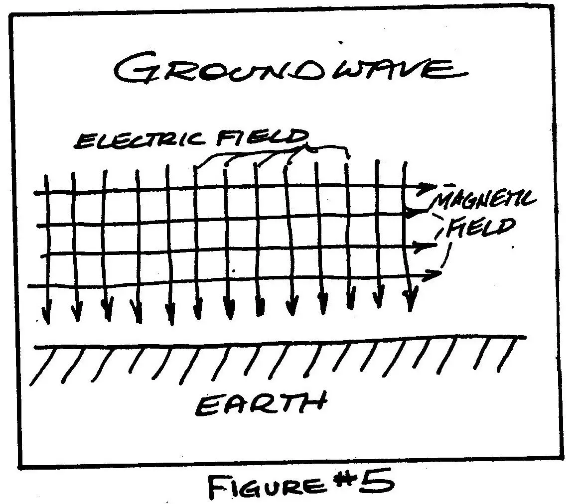
Another factor is the density of ionized layers. It varies during the day and night, causing signals to be reflected from different layers, at various heights, and varying intensities on each band and at each time of day. But, for this article, we will consider only the effects of antennas and only the range of 160 through 10 meters. Before studying the various antennas, a word about groundwaves. The laws of electro-magnetics require that, for a radio signal to travel across the surface of the ground, the electrical component must be perpendicular to the surface (Figure #5).
That means, that to produce groundwave signals, the radiator must be vertically polarized. A horizontally polarized antenna will produce stray vertically polarized waves, especially in some directions, but the groundwave effectiveness will be meager, Let it suffice to say that verticals produce groundwaves, and horizontals do not. Close-in contacts on 10-15 & 20(where attenuation is highest) would be better accomplished with a 16-foot vertical whip than a big yagi beam on top of a tower.
So, this leaves "skywave" contacts from 50 to 12,000 miles, to compare antennas for this purpose, radiation patterns will be used. There are two types of radiation patterns to be compared....vertical and horizontal. Now, in this case, "vertical" and "horizontal" are not referring to the polarization of the antenna in question, but rather the method of viewing the pattern of radiation.
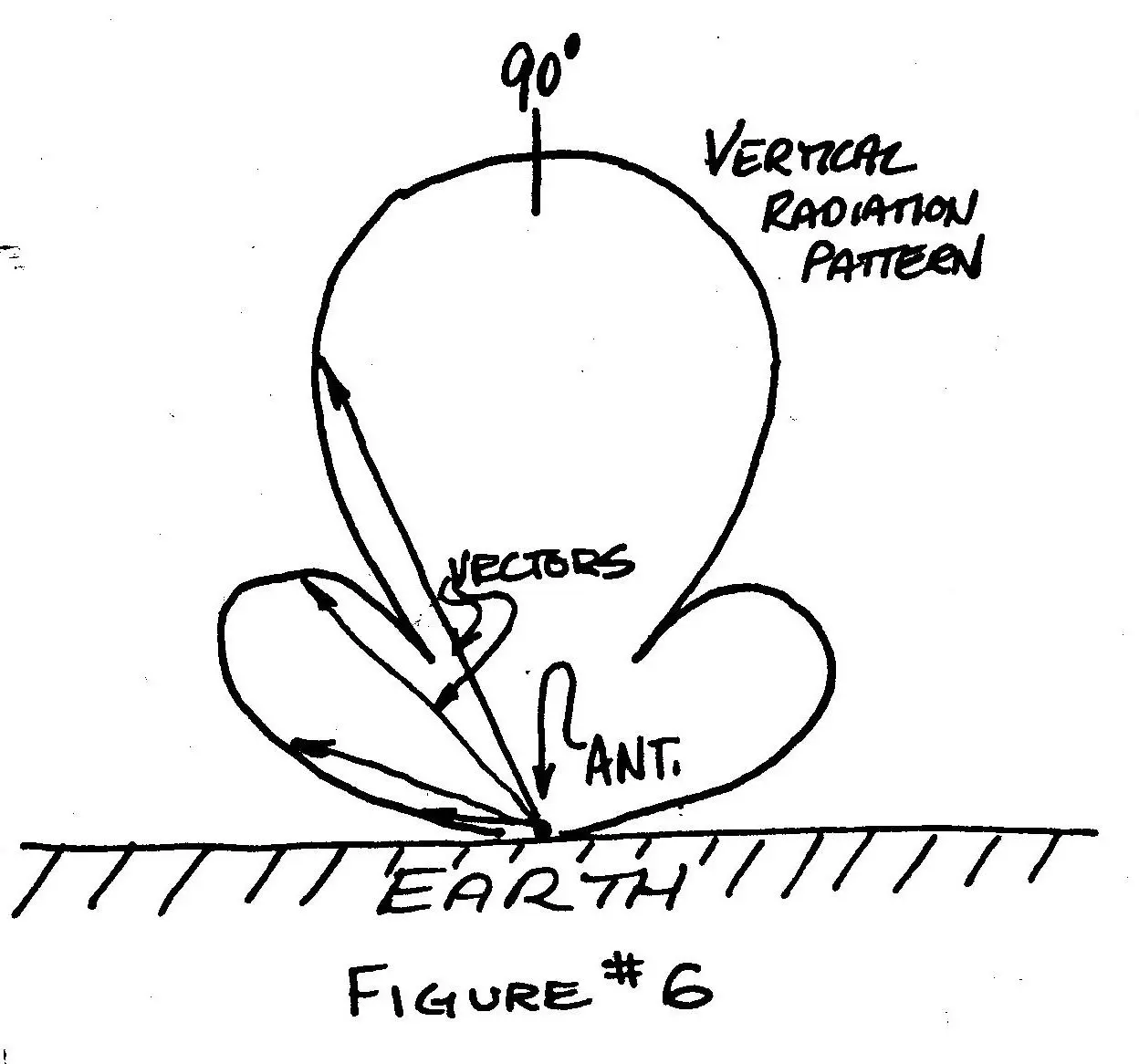
"Vertical" radiation patterns (Figure #6) view the antenna from the side, with the baseline being the earth's surface. The curved line describes the antenna's radiation pattern. It displays vector quantities. That is, lines drawn from the center point (antenna position) to any points on the curve can be compared. The longer lines (vectors) -: represent greater radiation. So, as can be seen in the example, vertical radiation patterns are most useful to indicate radiation from an antenna at various angles to the earth's surface. The antenna in Figure #6 is primarily a high-angle radiator.
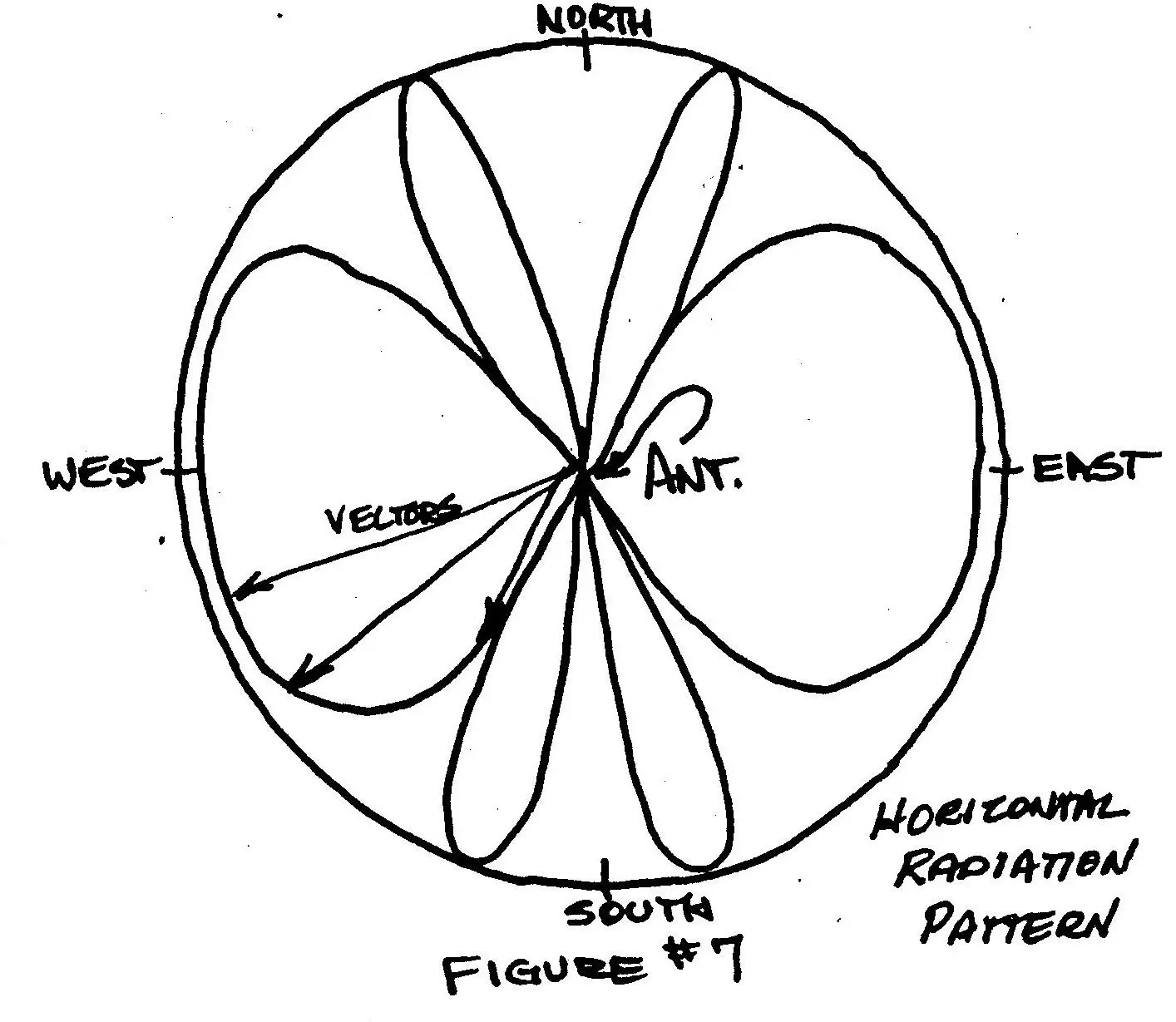
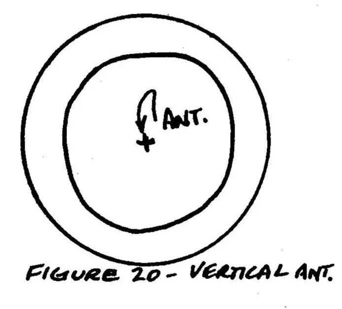
"Horizontal" radiation patterns view the antenna from above and describe the: radiation relative to compass directions (Figure #7). In this example, the antenna is running North and South and has major radication lobes to the East and West.
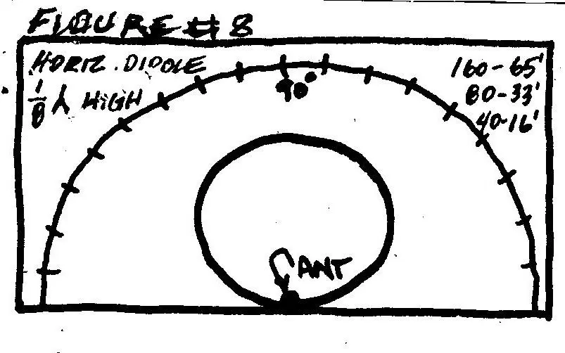
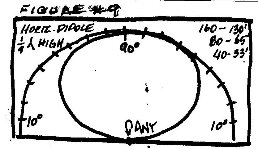
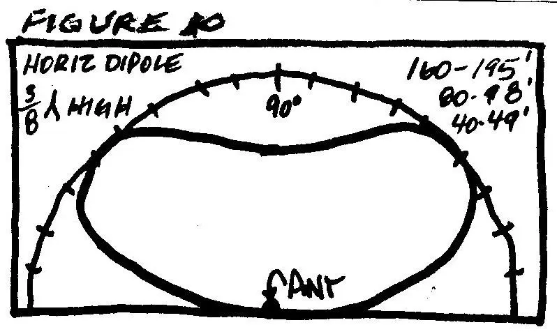
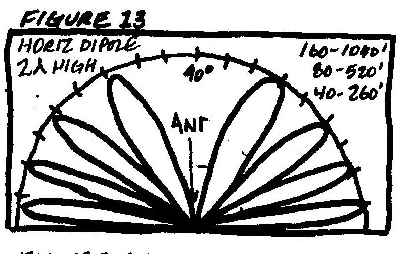
Previously we spoke on several versions of the dipole antenna. The radiation from these horizontal antennas was not described. Vertical radiation patterns for the horizontal dipole indicate that radiation angles vary with height above ground.
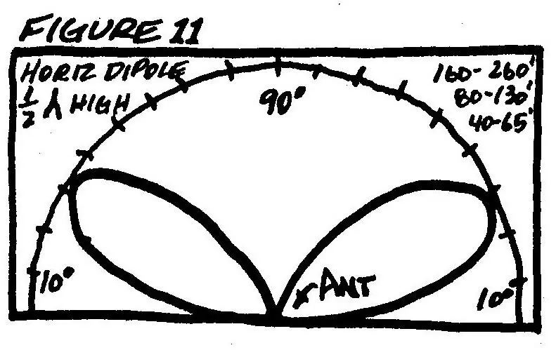
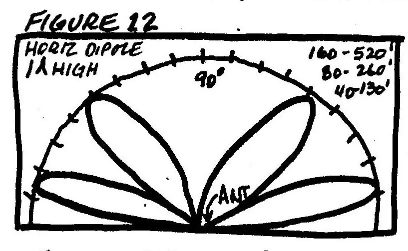
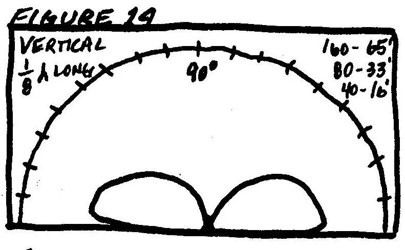
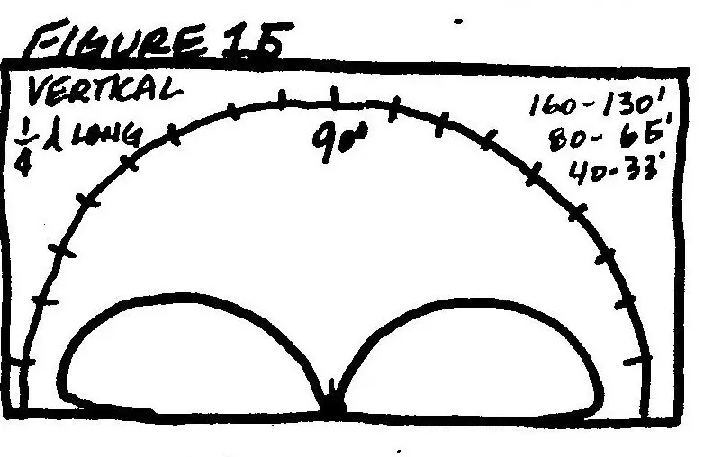
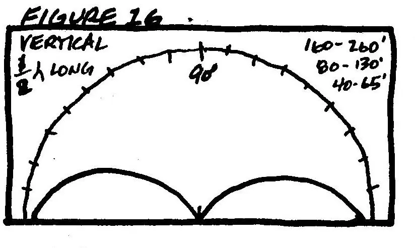
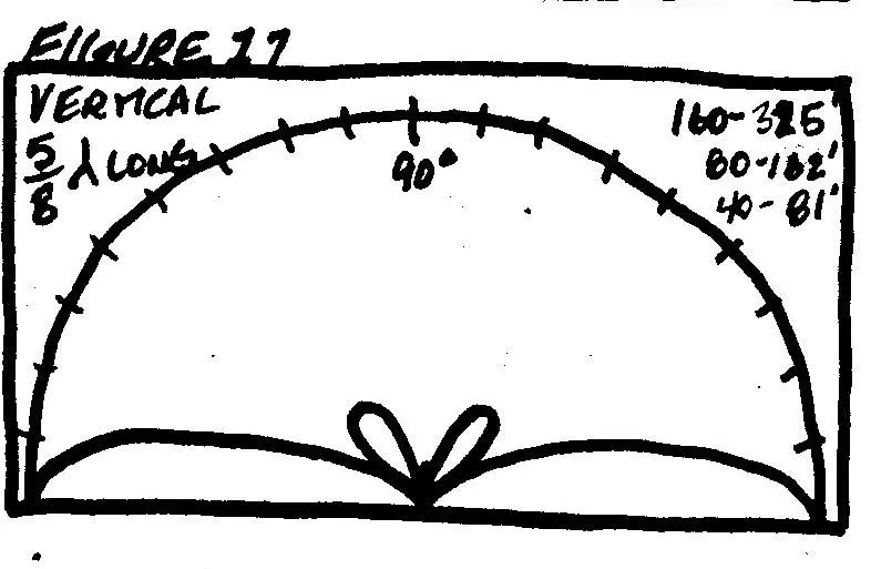
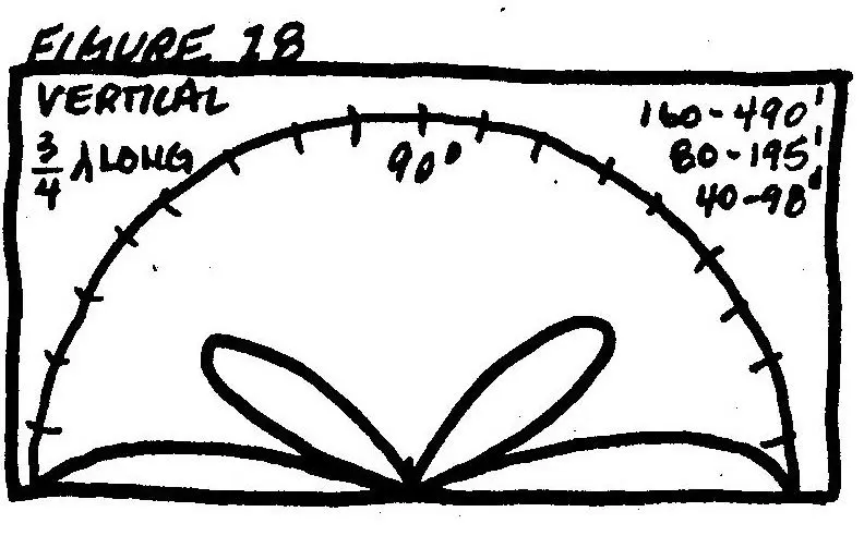
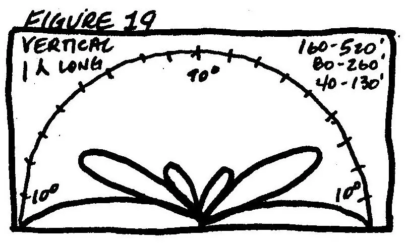
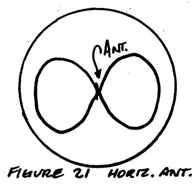
This is described in Figures #8 through 13. Height above ground in wavelengths is given for each example. Also, height in feet for 160, 80, & 40 meters is given for each. The examples show that for short skip skywave, (50 to 500 miles) the heights: represented by Figures #8, 9, & 10 would be best. And, for long skip (low angle) contacts, one-half to two full wavelengths high would be best. These heights would be practical on 20, 15, & 10, but, how many hams can put up an 80-meter dipole at 260 or 520 feet? By the way, beams have somewhat different patterns, but the same principle applies as far as radiation angle. Figures #14 through 19 show vertical radiation patterns for vertical antennas of various lengths. The examples show that • the vertical antenna is best for long skip DX and lousy for short skip, up to a height of five-eighths wavelength. Above that height, high-angle lobes begin to grow, with no additional low-angle radiation. "Horizontal" radiation patterns for vertical and horizontal antennas (Figures #20 & 21) show the generalized comparison.
Different versions of horizontal dipoles (inverted "y", double extended Zepp, etc.) will have various patterns but will remain directionally selective.
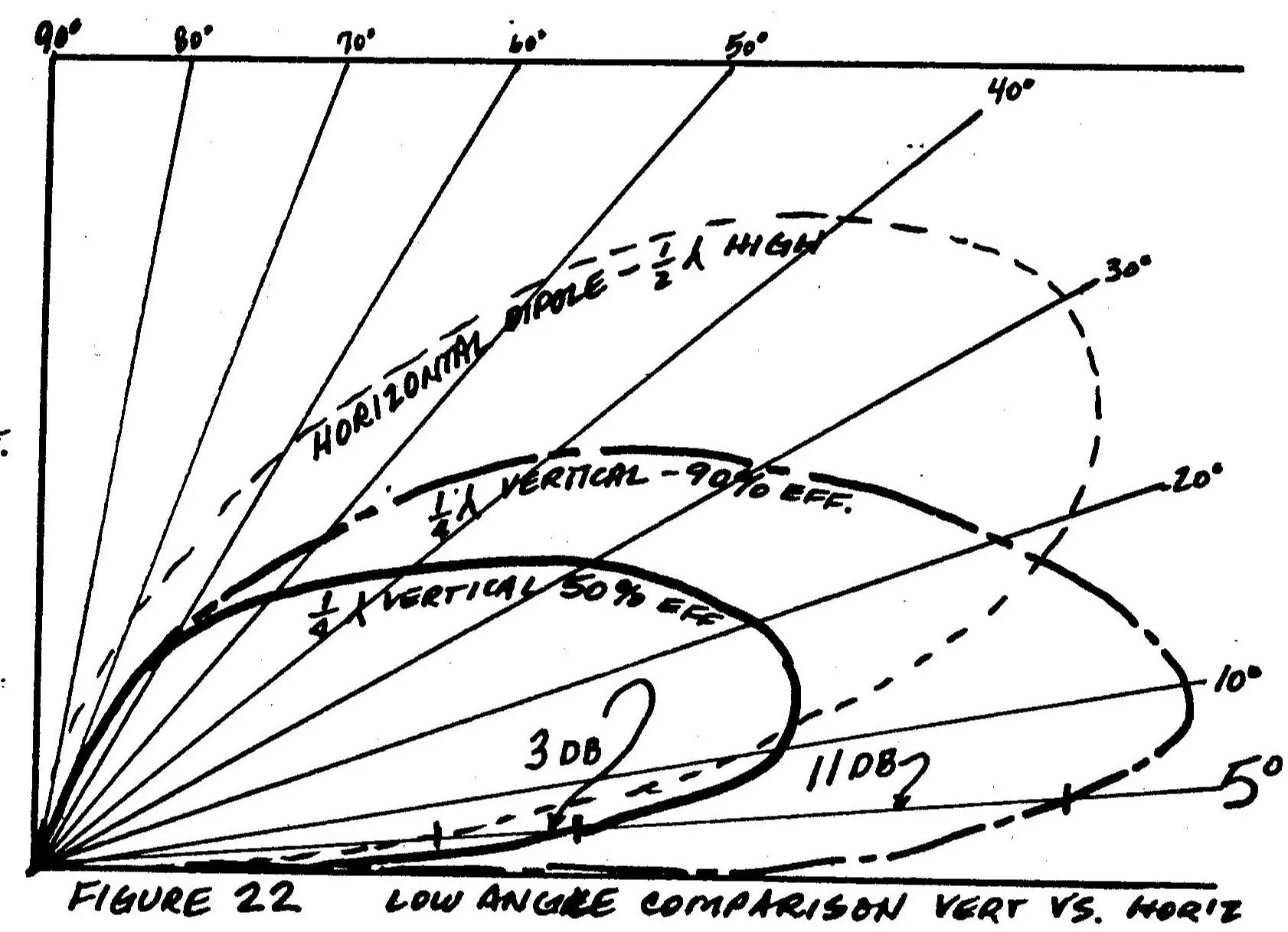
Now, for one last comparison. Figure #22 is one-half of a vertical radiation pattern (the other side is identical). Three antennas are plotted with the main objective to compare low-low angle (long DX) capability. This is the most difficult to achieve characteristic. One antenna is a horizontal dipole, one-half wavelength above ground. It is considered to be 100% efficient. The second antenna is a one-quarter wave vertical antenna with a good ground
system and is plotted as 90% efficient.
The third antenna is another one-quarter wave vertical, but with a poor ground system and is 50% efficient. The results are plain to see. At an angle of 5º the good vertical is ll db better than the dipole and even the poor vertical beats it out by 3 db.....and the verticals do it in all directions. Now keep in mind, for example, that for 40 meters the comparison is between a 33-foot ground-mounted vertical and a half-wave dipole, 65 feet high. Well, what conclusions can be drawn from this?
1. For close-in, groundwave contacts...use a vertical.
2. On bands where high angle reflection is commonly possible, like 160, 80, & 40, use low horizontal antennas for 50 to 500-mile work...as an example, a 50-foot high dipole on 80 meters.
3. For low-angle, long-distance work, use dipoles at least one-half wavelength high. (20mtrs--33 feet or better)
4. For 160, 80, and 40, the vertical may be a better practical antenna for low-angle work than the dipole.
For 20, 15, &10, the multi-element beam is a good bet, offering gain, rejection of unwanted signals, and multi-band-160.

All articles listed below are the works and property of Barry A. Boothe.
1. Mobile Antennas
2. Low Band Antenna Survey
3, Shortened, Loaded Antennas
4. Choosing an Antenna
5. Creeps and Weirdos (Tongue in Cheek)
6. The All Band Antenna
7. The Ultimate Ultimate Transmatch
8. The Invisible 20-Meter Beam
9. The Hidden Antenna
10. The Loop Antenna
11. Thinking About Basics
12. The Other Half
13. A Personal Look At Field Day
73, Barry