The One About the All Band Antenna, Balanced Line, Tuner, and a Unicorn
All Band Antennas, Balanced Line, Tuners, and Such
By Barry Boothe, W9UCW © A Long Time Ago in a... "You know the Rest"
I often get into discussions concerning matching problems when using a balanced feedline to feed an all-band antenna like a big dipole or loop, for instance. Recently a friend wondered why he was having trouble getting a decent match on his newly extended dipole. He had gone from an 80-meter to a 160 meter dipole. He said that previously, he had no problems getting a 1:1 SWR connecting a “4 to 1” balun to the feeders, running coax down to the tuner and onto the rig. I suggested that he might have been having trouble that he couldn’t see on an SWR meter and that some changes are in order if he is to realize the advantage of the enlarged antenna. He had some problem getting my drift so I went into more detail. Here are the main points related to an all-band antenna setup utilizing a balanced feedline.
1. The use of a balanced feedline on a dipole or a loop, for example, allows an almost zero loss setup that can be perfectly matched across a very broad spectrum of frequencies.... like maybe 160 through 10 or even 6 meters. Other advantages are related to the nature of balanced feeders, like a lack of radiation or of signal & noise pickup from the feedline. This is because the currents in the two wires in a properly operating system are equal and of opposite phases. Therefore, the fields cancel one another. Thus, there’s no radiation or reception from the feedline. Coax, on the other hand, does radiate and pick up unwanted noise unless it is feeding a purely resistive unbalanced 50Ω load. This is rarely the case, and almost never happens in an all-band antenna setup. More about that later.
2. At the radio end of the balanced feedline feeding an all-band antenna, there will be seen an infinite variety of impedances as you move across the frequency spectrum to be used. At each frequency, the impedance is a combination of a resistive component and a reactive component. The reactive component must be “tuned out” or nullified for the most efficient transmission of energy. It is possible that at some frequency between, say, 1.8mHz and 29.7mHz that the impedance will be 50Ω or 200Ω or 300Ω resistive only (no reactance), but it is extremely unlikely.
3. The impedance will vary across the spectrum from perhaps under 50Ω to more than 1000Ω with reactances of high negative to high positive values. The impedance will "roller-coaster" up and down many times across the frequency spectrum.
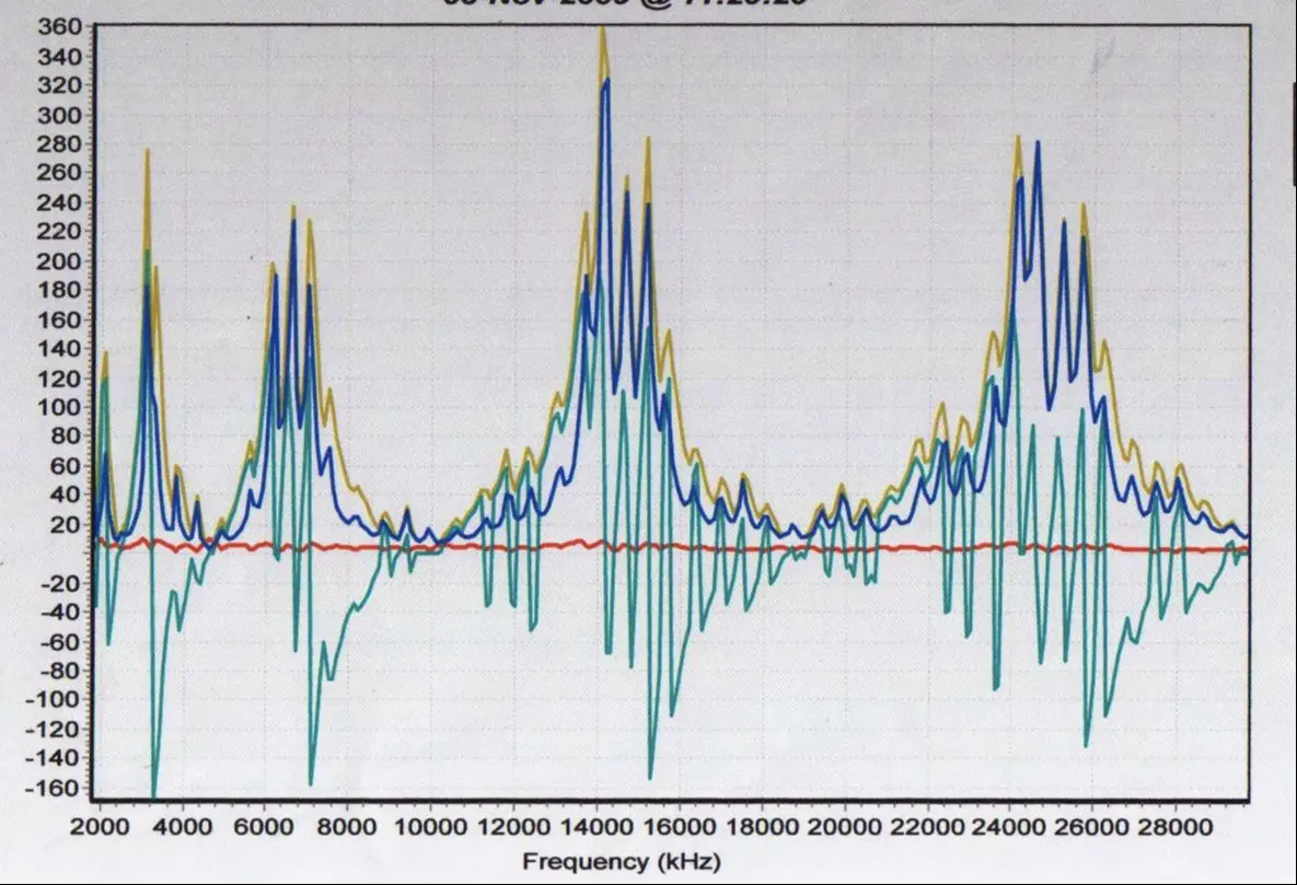
Here is an example. This is the analyzer plot for our big horizontal loop in Santa Rosa taken at the “shack” end of the feedline. The plot covers 160 through 10 meters. Notice that the impedance (tan) goes from lows of about 15Ω to a peak value near 20 meters of 360Ω. The reactance varies across the spectrum from +180 to -160.
The pattern is determined by the length, size, shape, height and characteristics of the antenna and the feedline. The point is, the impedance at the end of the feedline has to somehow be "matched" to the output of the radio on each and every frequency of operation.
4. Because the output arrangement on modern gear is all but exclusively unbalanced, and usually at 50Ω, two things must happen. First, some mechanism must convert from BALanced to UNbalanced between the feedline and the radio. Secondly, whatever impedance is encountered at the incoming balanced feedline must be transformed to 50Ω. These two tasks are usually done by some sort of “antenna tuner” or “transmatch.”
5. The mechanism for the first task will be the “BAL-UN.” Excuse me while I climb up on my soapbox and talk about baluns.
The balun can be designed to go from a specific impedance to the same or a different specific impedance. Commonly, when one refers to a “1 to 1 balun” in ham radio setups, 50Ω to 50Ω is implied. Similarly, a “4 to 1 balun” most commonly means a 200Ω to 50Ω impedance. But, a 4:1 could be a 75Ω to 300Ω unit, or a 50Ω to 12.5Ω unit and the list of possibilities goes on and on. The point here is that baluns are designed for specific impedances, and as it turns out, for use on specific frequencies.
Having said that, I must add that broadband baluns have been designed using modern materials. It's possible to cover more than one, and in some cases, several ham bands with a balun without losing an excessive amount of power. It's even possible to make somewhat of an excursion from the design impedance. Let's see how that plays out.
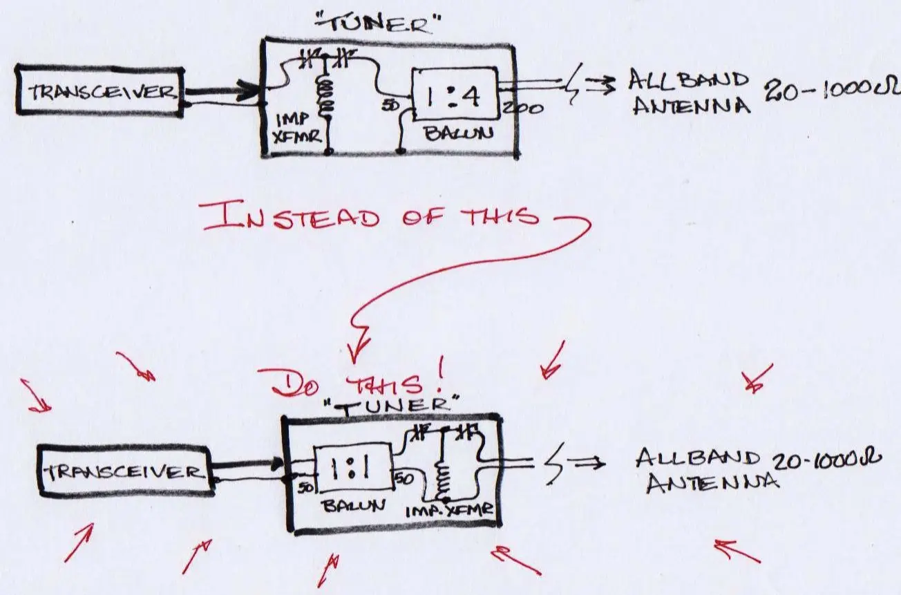
For instance, consider the common 4:1 balun hung on the output of single-ended (unbalanced) tuners to feed balanced line antennas. This has been the way the vast majority of commercial tuners have been built for the past 30-40 years. The tuner makers claim or at least imply that the "all band 4 to 1" balun in their box covers 160 through 10 meters, and takes the balanced impedance encountered at the tuner output terminals and brings it down to one-fourth that amount. In the process, it is changed from balanced to unbalanced, leaving the "tuner" part of the box to take what comes out of the balun and transform it to 50Ω.
There are some problems with all this. First of all, most of the baluns in question have been wound on powdered iron toroidal cores. That means that the range of frequency over which they will do their job without much loss is 2 or 3 to 1. Like 80 & 40, or 40 through 15, or maybe 20 through 10 meters, depending on how they were made. If they were wound on ferrite cores of the right mix, they might cover a 10 to 1 frequency range.
The second issue is that those baluns are universally designed for 200Ω balanced to 50Ω unbalanced. That means the only case where they do what they were designed to do is when the impedance at the radio end of the feedline is 200Ω. An excursion of 20% could be tolerated, although with greater losses experienced above 10mHz. This situation does not lend itself well to multi-band... or for that matter, even multi-frequency setups.
One might counter the fact that 1:1 SWRs are nearly always achieved across all the bands in the HF spectrum with these kinds of tuners. That's true, but the great god “SWR” is not the only idol to be adored. If truth is known, in many cases where the meter shows 1:1, the antenna connected to the tuner/balun is acting like a big blob of metal or a long wire... not at all like it was designed to operate. Meanwhile, the balun and parts of the tuner are suffering losses, and heat plus subjected to excessive voltages. SWR does not equate with efficiency!
Okay, I'm giving you more information than you asked for... but it's important to understand what's going on in typical setups. The bottom line is, in the case of a multi-band antenna fed with the balanced line, no fixed impedance balun can cope with the excursions of impedance at the radio end of the feedline without great losses, possible voltage arcs, and other problems.
This still leaves the task of going from balanced to unbalanced to satisfy the radio. The nice thing about this is that simple, inexpensive baluns can be easily constructed that will provide the conversion, 1:1, or 50Ω to 50Ω over the entire HF spectrum with little to no losses. So, let’s put one of these at the input to the “tuner,” where the output of the 50Ω unbalanced transmitter/transceiver is connected, and then deal with the second task of a “tuner.” That is, transforming the impedance at the end of the balanced feedline to 50Ω balanced, the output of the 1:1 balun.
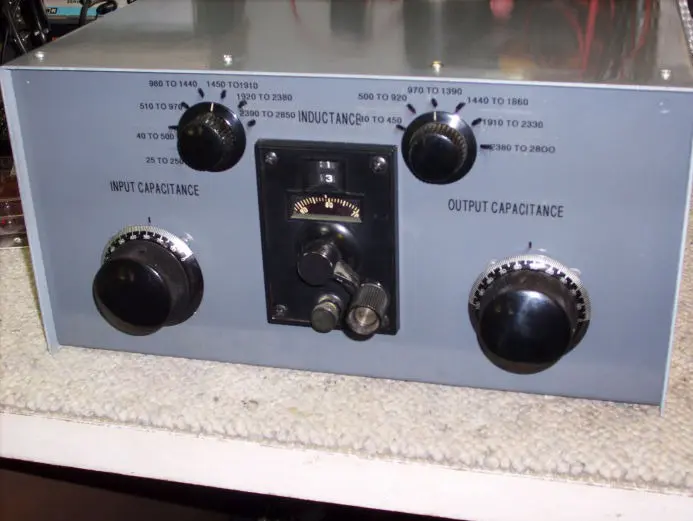
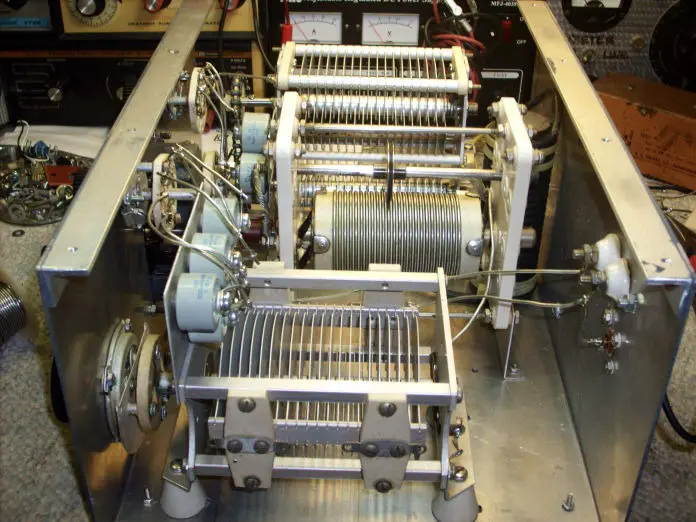
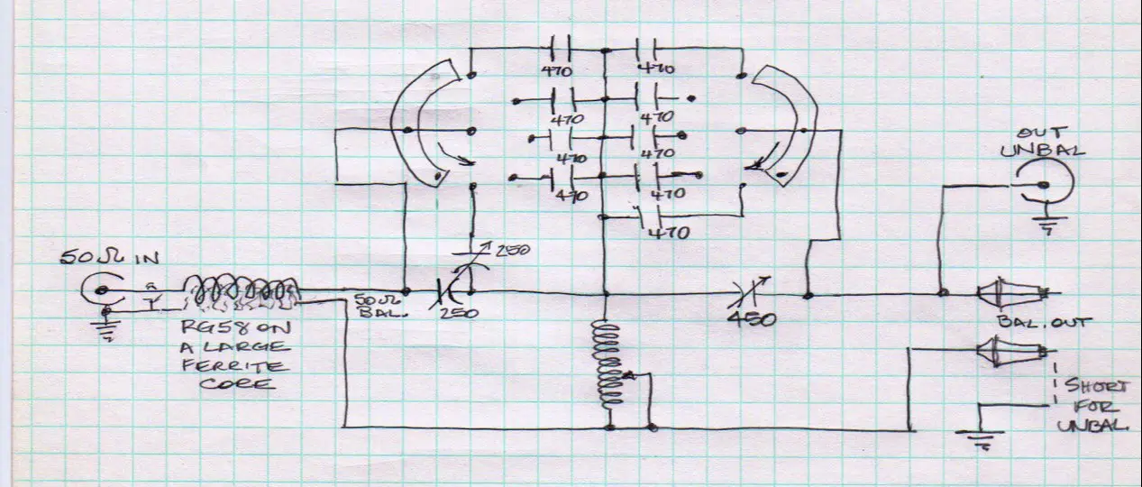
6. What must be connected between the feedline and the balun is an adjustable impedance transformer... we call them antenna tuners or transmatches or some such. It may be a balanced double "L" network, a balanced "T" network, or an unbalanced "L" or "T" like the Ultimate or SPC Transmatch, as long as it is isolated from the ground. There are a few variations in use, but any one of them can transform the impedance encountered at the end of the feedline, whatever it is, to 50Ω resistive, for example, still balanced.
There’s certainly lot more to this subject, but for now, you have the basics concerning using tuners with balanced feeders to all band antennas. If you have questions to which I might help to find answers, e-mail and I’ll do my best.
For now, Happy Holidays, Happy New Year, and Merry Christmas. 73, Barry
Questions or comments?
W9UCW@arrl.net
(1) “Transmission Line Transformers,” Second ed., 1990 ,Jerry Sevick, W2FMI
There is one more notable device to mention in this context. That is the link-coupled, resonant tuner that has been around since time immemorial. Even though it requires a bit more setup and often means big plug-in coils for each band, this tuner (impedance transformer) does both the matching of impedance as well as the BAL-UN conversion. And it does it with the best loss figure of any design as well as providing a narrow passband. This last feature means a reduction of spurious or harmonic emanations on transmit as well as a reduction of front-end overload caused by strong off-frequency signals like broadcast stations and local hams.

All articles listed below are the works and property of Barry A. Boothe.
1. Mobile Antennas
2. Low Band Antenna Survey
3, Shortened, Loaded Antennas
4. Choosing an Antenna
5. Creeps and Weirdos (Tongue in Cheek)
6. The All Band Antenna
7. The Ultimate Ultimate Transmatch
8. The Invisible 20-Meter Beam
9. The Hidden Antenna
10. The Loop Antenna
11. Thinking About Basics
12. The Other Half
13. A Personal Look At Field Day
73, Barry